
Compressor Refurbishments
COMPRESSOR
REFURBISHMENTS
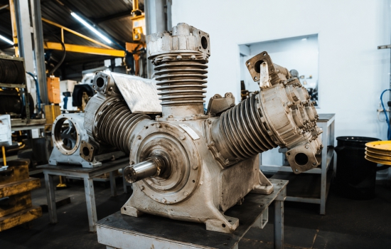
Figure 1: Unit received for refurbishment,
and sandblasted for stripping.
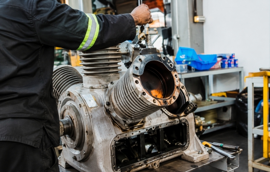
Figure 2: Stripping of unit.
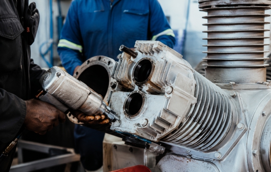
Figure 3: Stripping of unit and taking out the
internals.
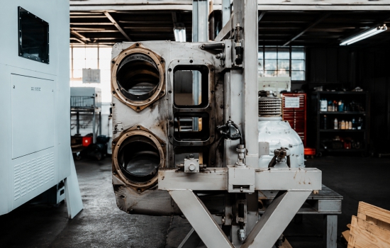
Figure 4: Unit being bolted to our assembly/
disassembly table for ease of use.
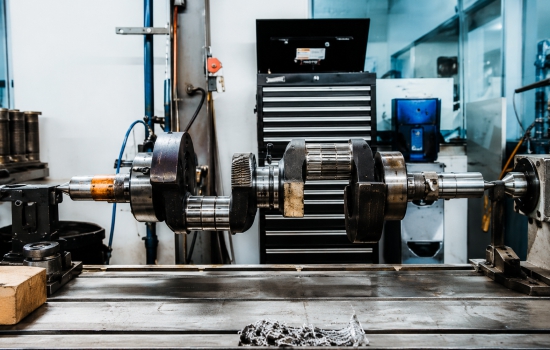
Figure 5: Crankshaft getting placed between
centers for polishing along with inspection
and micrometer measurement to see if the
crankshaft complies with the OEM spec.
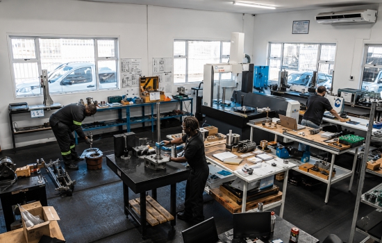
Figure 6: All parts that come off the
compressors, are taken to our Quality control
room, where we will inspect, and measure
each component.
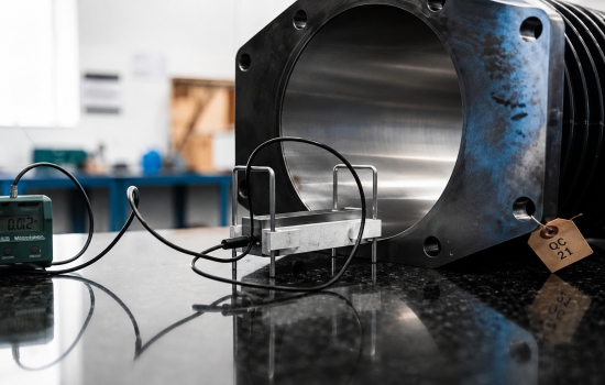
Figure 7: All items that required to adhere to
a certain surface finish is measure using our
surface roughness machine to ensure all parts
adhere to the correct specification.
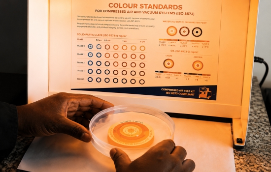
Figure 8: Inspection of compressor valve seat
using shadow graph machine.
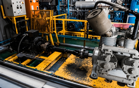
Figure 9: Wabco 6CD on our compressor test
bench, units get tested roughly for 6-8 Hours.
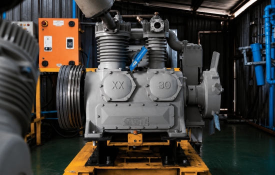
Figure 10: Wabco 4CD on our specially
designed bench for units which is driven via
a pulley system.
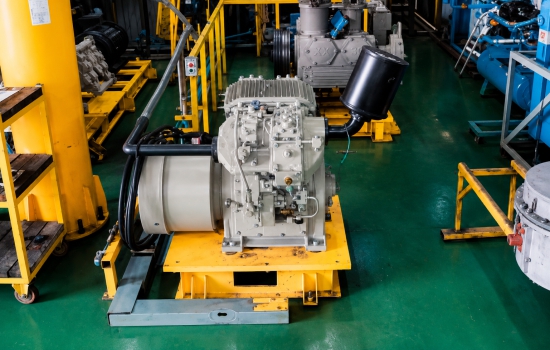
Figure 11: Testing of the Gardner Denver and
Wabtec units that are driven via the General
Electric (GE) Motors, our test bench has been
approved and certified by General Electric
(GE).
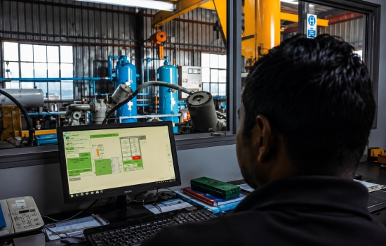
Figure 12: Compressors running on test,
where we control via computer systems,
we are able to measure the oil carry over,
vibration, oil pump pressure, air pressure,
voltage, discharge air temperature, dual
speed being low speed and high speed.
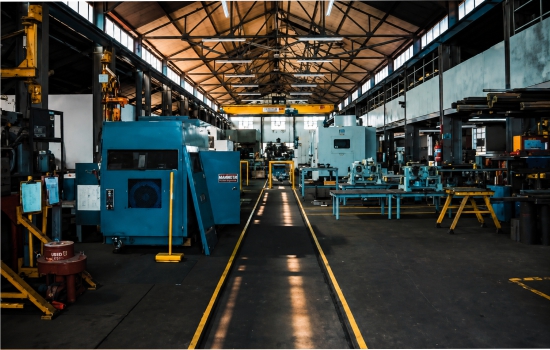
Figure 13: Over view of the compressor
division.
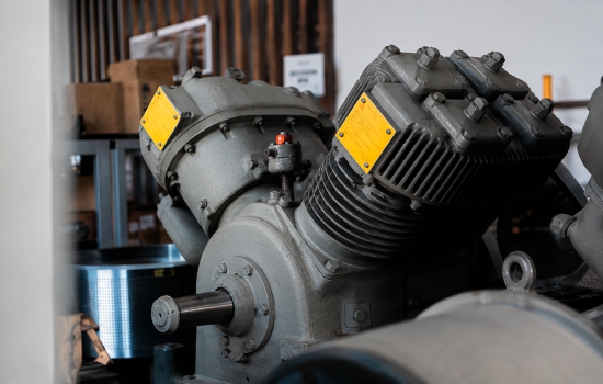
Figure 14: Units In dispatch get bolted down
to a heavy duty pallet for transportation, all
the Inlet and outlet ports get blocked off to
ensure no dirt can come into any of the ports.
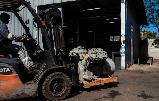
Figure 15: Units getting ready to leave
dispatch to go to the customer.